Prelab
In the sixth lab, we built upon the PID principles that we learned about through lab five, but instead of implementing a linear PID controller that maintains a certain distance from a wall, we are now focusing on building a controller that will maintain the car's orientation, even when we kick it around. Similar to the previous week's lab, careful tuning was required to ensure that the car's response and adjustments were reasonably close to optimal, and much was learned about the use of the gyroscope in the implementation of orientation control.
Like with the previous lab, before we could even consider getting started with the implementation of the sensor data and math itself, we would need a reliable and consistent method of communicating from our Python code across to the Artemis Nano Board. To this end, we utilized a near identical setup as before involving a Bluetooth command that could be called on our Python side with necessary arguments that would facilitate fine-tuning of our PID parameters. Additionally, we would be receiving data on the PWM output and the yaw output from the onboard IMU to see how our controller performs.
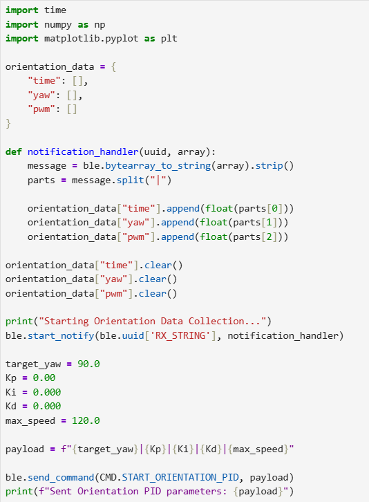 Python side receiving and sending inputs.
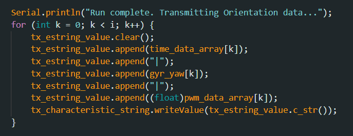 Arduino side sending valuable data.
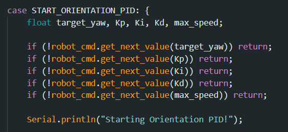 Our new Bluetooth command.
It is important to note that with this current method of communicating, we are effectively blocking off the robot from being able to receive any other command while running, which is not how we would run normally. For testing purposes however, this simplified method is perfect as it allows us to worry more about the exact math involved rather than any bugs that might occur due to the more complex code. Once we have sufficiently refined our PID controller, a more useful, non-blocking method of communication will be implemented.
Setting Up DMP for Input Data
Because we are dealing with orientation, as opposed to last week's lab where we used the ToF sensor to receive feedback on the car's distance to the wall, we will be using the IMU that we tested a couple of weeks ago in order to continuously receive orientation data, specifically the yaw of the car. However, as we discovered in the previous lab while testing, the gyroscope onboard the IMU experiences drift that unfortunately cannot be simply rectified with our accelerometer unlike the pitch and roll. Thus we need to make use of the IMU's built in digital motion processor or DMP, which is capable of error and drift correction by fusing readings from all the IMU's different sensors, perfect for our orientation control which will need reliable data.
By default, the DMP is disabled due to requiring a lot of memory, so our first step in initializing it is by modifying a line of code in the ICM_20948_C.h header file as seen below:
 Uncommented line in header file.
Afterwards, the setup_IMU function that is called everytime we start up the Artemis Nano board was updated to include the DMP initialization code provided in one of the example functions:
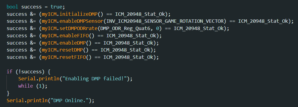 Initialization of DMP in the IMU setup function.
Finally, in order to receive values that will be easy to use, we implemented an additional function called update_yaw which receives the orientation values in quaternion form before converting them to Euler angles (though only doing this for yaw since that's the only relevant piece of data). That then updates a global variable which can readily be accessed by our PID controller. Something important to note is that with the DMP, the sensor data is sent through a FIFO queue. Given the rapid speed at which the board can produce data (faster than our individual sensors), this means that if left alone there is a risk of the FIFO filling up and overloading the DMP if we don't process the data quickly enough. As a result, when receiving data, instead of just checking once every function call or adding a delay which could slow things down, update_yaw utilizes a while loop to ensure that the FIFO is empty (and that we receive the most up to date data) before exiting the function. By emptying out the FIFO queue like this, we can ensure that we won't experience an overflow of values.
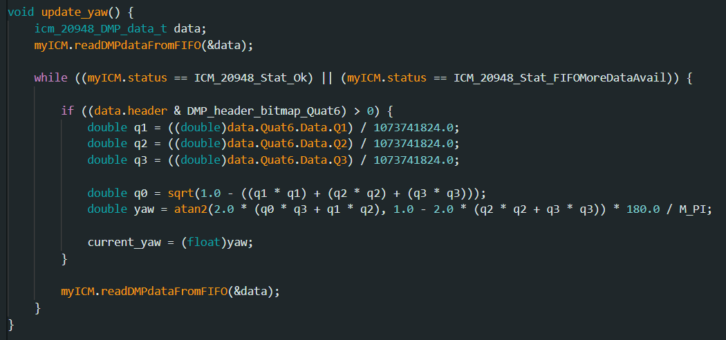 Converting yaw to Euler angles and ensuring FIFO queue is emptied.
Implementing Orientation Control
Like in the previous lab, the method of implementation would be through an incremental approach where we would slowly add more complexity to our code in order to facilitate debugging. The first and easiest step in performing orientation control is through the use of the Proportional term in the PID controller. Like in the previous lab, there were many specific details that we added in order to refine the initial controller (as seen in the code below). The first of which would be recognizing the fact that with orientation, once past 180 or -180 degrees it loops around, which would cause a massive jolt given a normal implementation of the Proportional term. As such, this is accounted for in the code. Additionally, like before when it comes to our final output PWM value, we rescale it based on our deadband, which was found to be 100 in a previous lab. However, because we ended up scaling one of our motors down by 0.833, that means the deadband limit needs to be raised, which is why in our implementation it is set as 120. A small margin of error is accounted for to prevent jittering once really close to the desired yaw value, and like before, the max speed is limited to ensure safe testing.
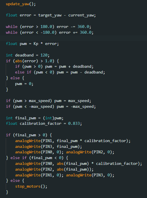 Implementation for Proportional term of orientation controller.
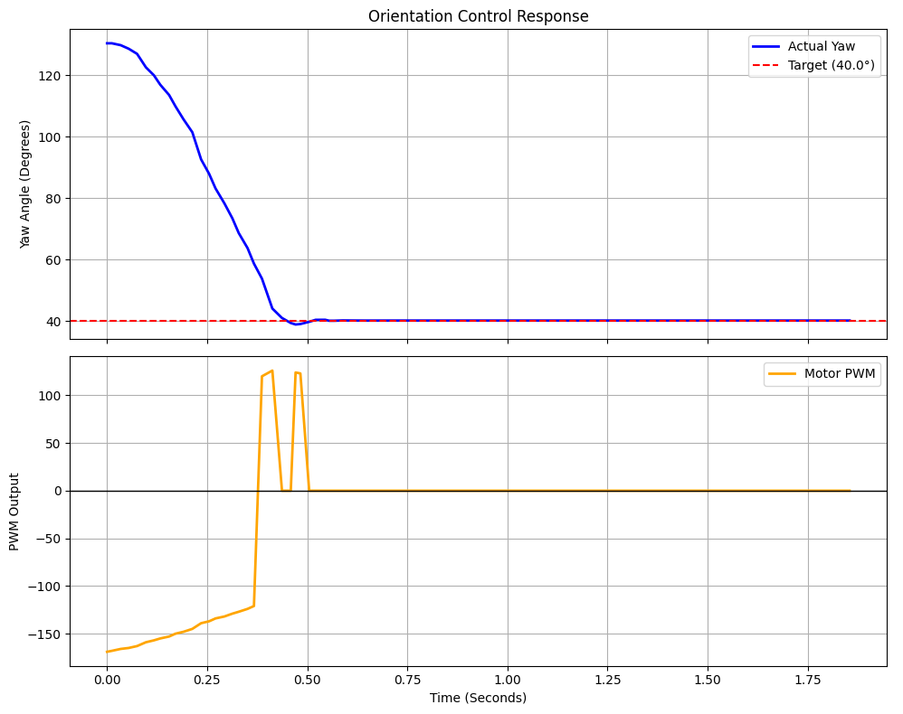
Like in the previous lab, when picking our Kp value, we wanted to select a value that would cause the car to overshoot by some margin. This was because we knew that damping would be implemented later once the Derivative term was introduced, so we could afford to sacrifice pure pinpoint accuracy for increased rotation speed. As a result, the final Kp value we chose, 0.5, caused the car to oscillate by some margin, but this was expected.
Showcasing the car using the Proportional term for orientation control.
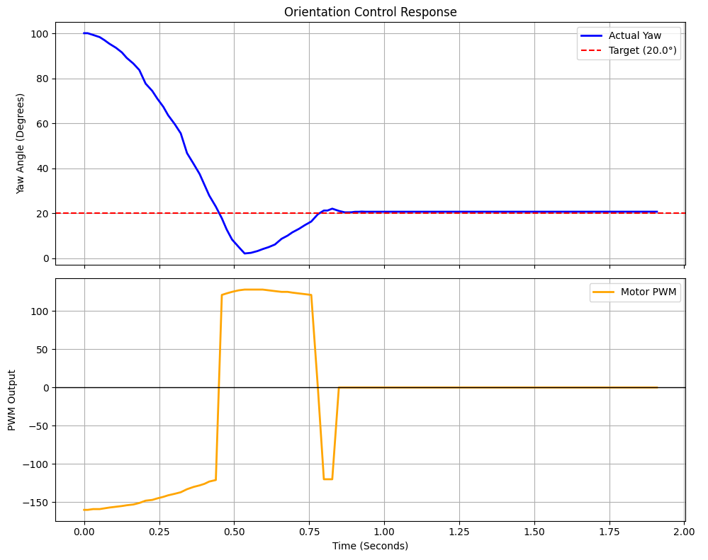 Results after using only Proportional Term for orientation control.
The next step would be to dampen this oscillation effect by introducing the Derivative term. In order to prevent any derivative kick that might occur as a result of weird initialization effects and also to introduce safety guardrails in general, a max rotation speed was introduced to limit how much the Derivative term could affect the output PWM. This was done to future-proof when we would implement changing between multiple target yaws, which could potentially lead to sudden jolts and skyrocketing derivatives. Additionally, in order to filter out noise, the same low-pass filter as last lab was implemented.
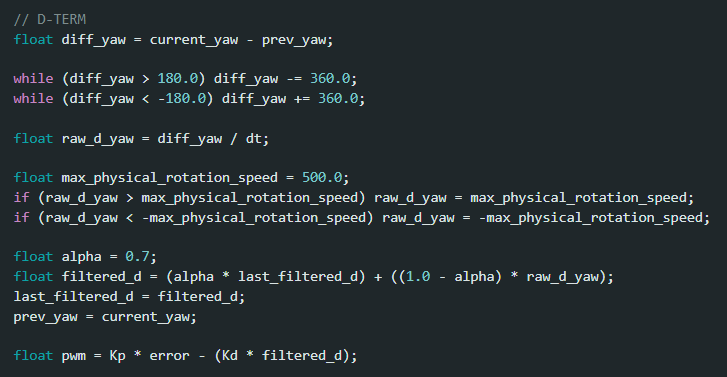 Implementation for Derivative term of orientation controller.
Fine tuning the exact Kd value required us to see how the car reacted when nearing the target yaw. Too high of a Kd value and the car would actually overcorrect and turn the other direction before hitting the yaw target, and picking too low meant that we still had the major oscillations as before. As a compromise, a value of 0.0275 was selected and found to be relatively good enough to ensure stability. See the result below.
Showcasing the car using the Proportional and Derivative Term for orientation control.
 Results after adding Derivative Term for orientation control.
As seen in the results above, this implementation of the orientation control was already very solid and produced good results. Consequently, it was decided to avoid implementing the Integration term as it would introduce more complexity and potential issues for very little gain since we had already attained a good level of accuracy.
In order to further test our implementation, the code was allowed to run for some time while we would kick the car around to see how it would react and readjust. As seen below, the results are satisfactory.
Showcasing the car's orientation control while getting kicked.
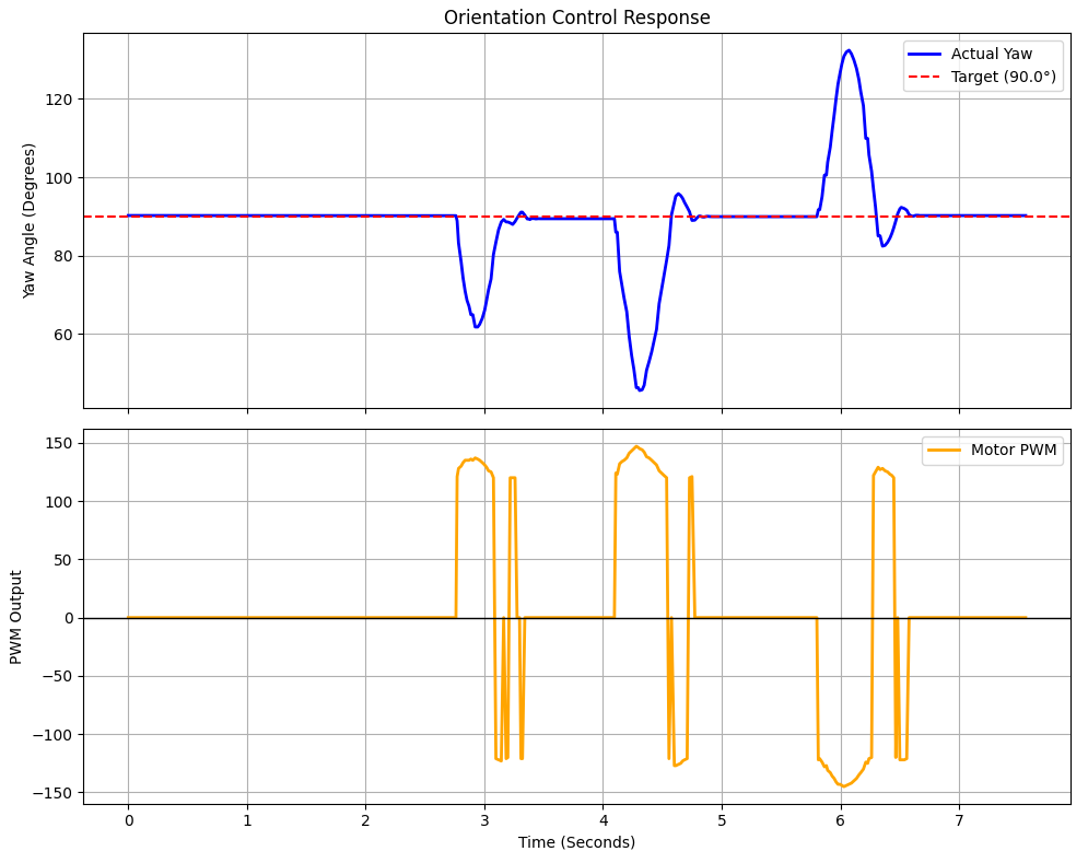 Results of kicking the car around and its adjustments.
Non-Blocking Implementation
Now that we've implemented a really solid version of the orientation controller, we could move back our focus towards the communication method and ensuring that it would be non-blocking, allowing us to not only add in more features in the future, but also to adjust the target yaw whenever we please, an important feature for the future. The first step was to convert the regular Bluetooth command we had to one similar to that which we had implemented in a previous lab, where calling it would simply raise a flag that we know wanted to control orientation. The same parameters we had sent would also be packaged along with the command call, and those would be set to global variables that would be accessed by a regular function, which would be repeatedly called within our main loop and would contain our orientation control implementation (essentially the same as before). When finished, we would send over a stop command that would turn off the flag to control orientation and then that would send over the data we would want. See below for the implementation.
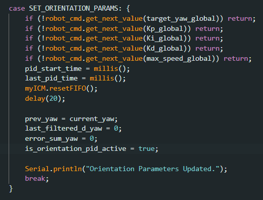 New Bluetooth command to start orientation control.
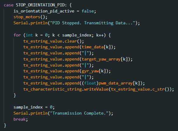 New Bluetooth command to stop orientation control and return data.
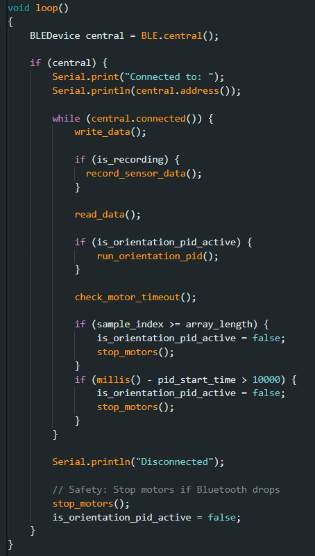 New main loop that would run our orientation control program in a non-blocking way.
As part of our data collection, we measured the average latency between the different samples collected through this new implementation and as seen below we had an estimated sampling rate of around 362.40 Hz, which is a considerably higher number than what we had gotten in the previous lab when it came to doing linear PID control. Not only does this highlight the efficient speed of the data received through the DMP, but it also further justifies the use of a non-blocking loop for our implementation, since we can more easily manage receiving data and correcting the car based on multiple different sensors operating at different frequencies.
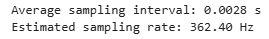 Calculated average latency and frequency of our new implementation.
The major advantage of this new implementation for this lab specifically was that it allows us to adjust the target yaw dynamically, which would be extremely useful in the future. The Python code was adjusted and the results shown below.
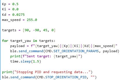 New Python code to adjust the target yaw dynamically.
Showcasing the new implementation with multiple target yaws.
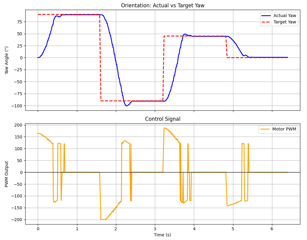 Results of our test with the new implementation.
Overall, this lab was very insightful in reinforcing the concepts we had learned about PID control in the previous lab, and it was also very interesting to see how the different implementations of communication affected what we could do with our programs. Seeing how much more useful the non-blocking version of our implementation was emphasized how good design choices at the beginning of a project can really shape the ease in which you can accomplish future tasks.
Katherine Hsu's website from SP25 was used to help inspire elements of this lab.