Prelab
In the fourth lab, we introduced open loop control to our robot through sending Bluetooth commands via our Artemis Board. To this end, two motor drivers needed to be integrated into the systems such that their inputs could be controlled by our microcontroller and their outputs could drive signals to the car's motors.
The first step would be to develop an idea of how exactly each component would be hooked up into the system. As seen in the schematic below, both motor drivers would be configured nearly identically except for the specific pins to which their inputs would be connected to. As instructed, the matching inputs and outputs of the motor drivers (A1 and B1; A2 and B2) were shorted together, and the inputs were connected to the Analog GPIO ports of the Artemis board, which were confirmed to have the PWM functionality that we would need for this lab. The A0 and A1 pins were selected to connect to the first motor driver, while the A2 and A3 pins were selected for the second.
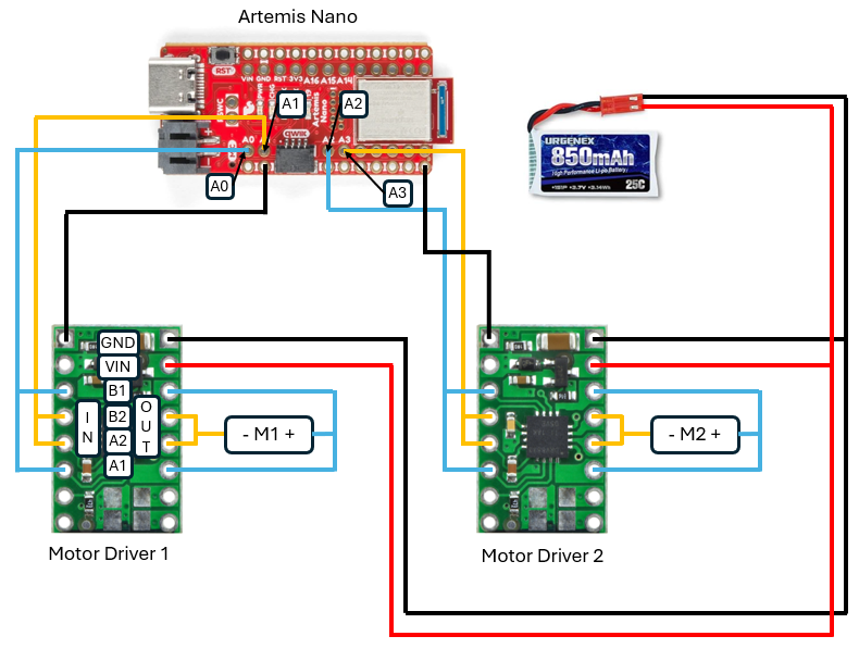 Wiring Schematic of the Motor Drivers.
As shown, the motor drivers would be powered by an 850 mAh battery that is separate from the battery used to power the Artemis board itself. This is because the motors will draw a high amount of current and could thus cause a lot of interference or electrical noise for the Artemis if they were plugged into the same power supply. This would be harmful to our ability to collect accurate and real-time data, so separate batteries are used to prevent this issue.
Lab 4
Generating PWM Signals
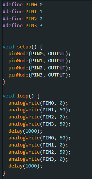
Before we can test out the motors of the car, we first need to verify that our motor drivers are capable of driving PWM signals. In order to test this, the code shown below was used to generate PWM signals which would then be probed using an oscilloscope. Instead of using a battery, we first used an external power supply in order to power the motor driver. Since the voltage of the battery we would end up using for the system was listed as being 3.7 V, that was the voltage that we set the power supply to.
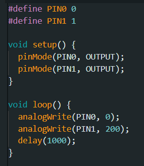 Code used to test PWM signal.
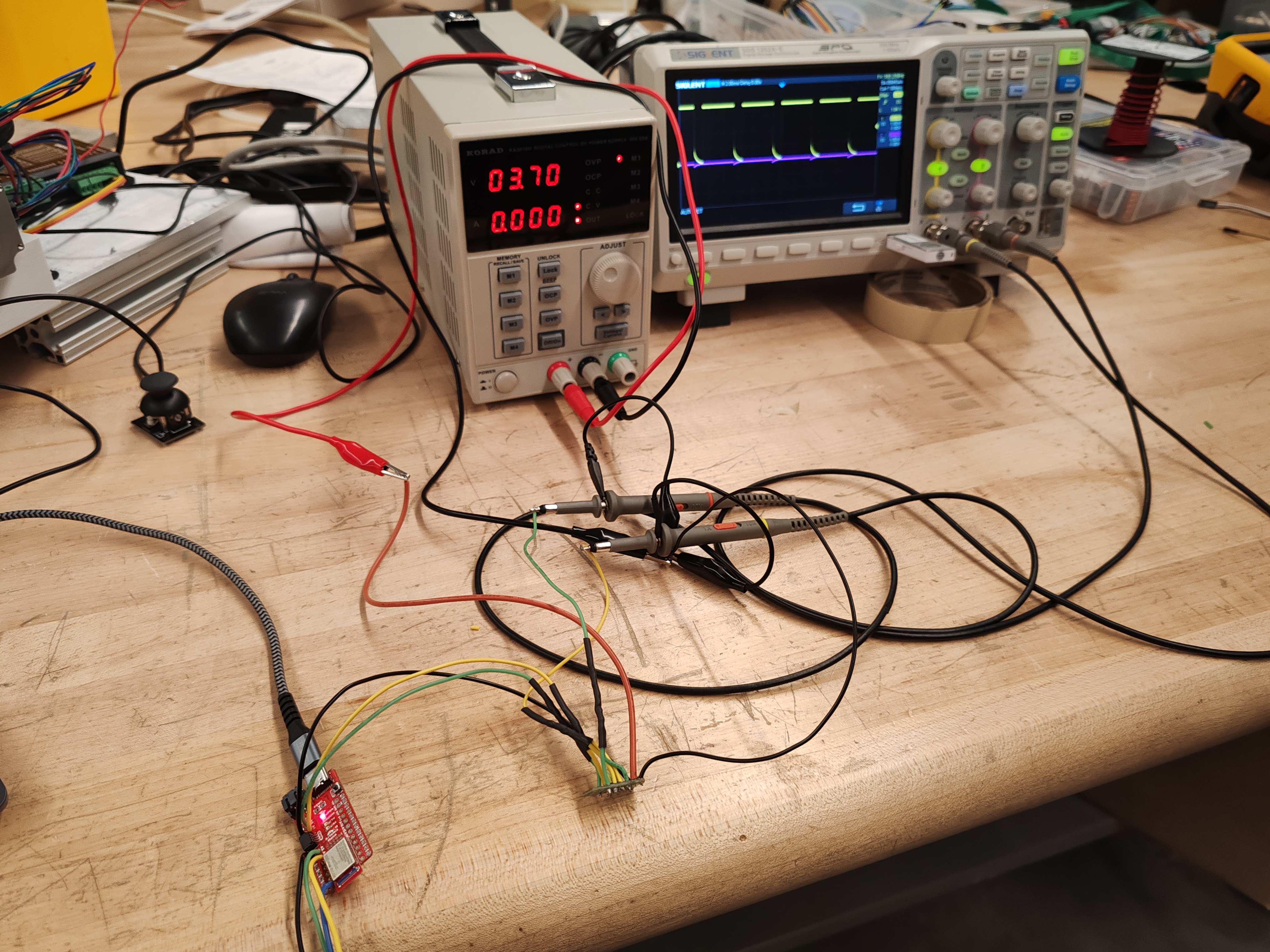 Setup of the Oscilloscope.
Shown in the picture below is the resulting signal from our oscilloscope. It is consistent and as we expected. The same test was performed for the motor driver, with the same code being used except that the pin numbers were changed accordingly.
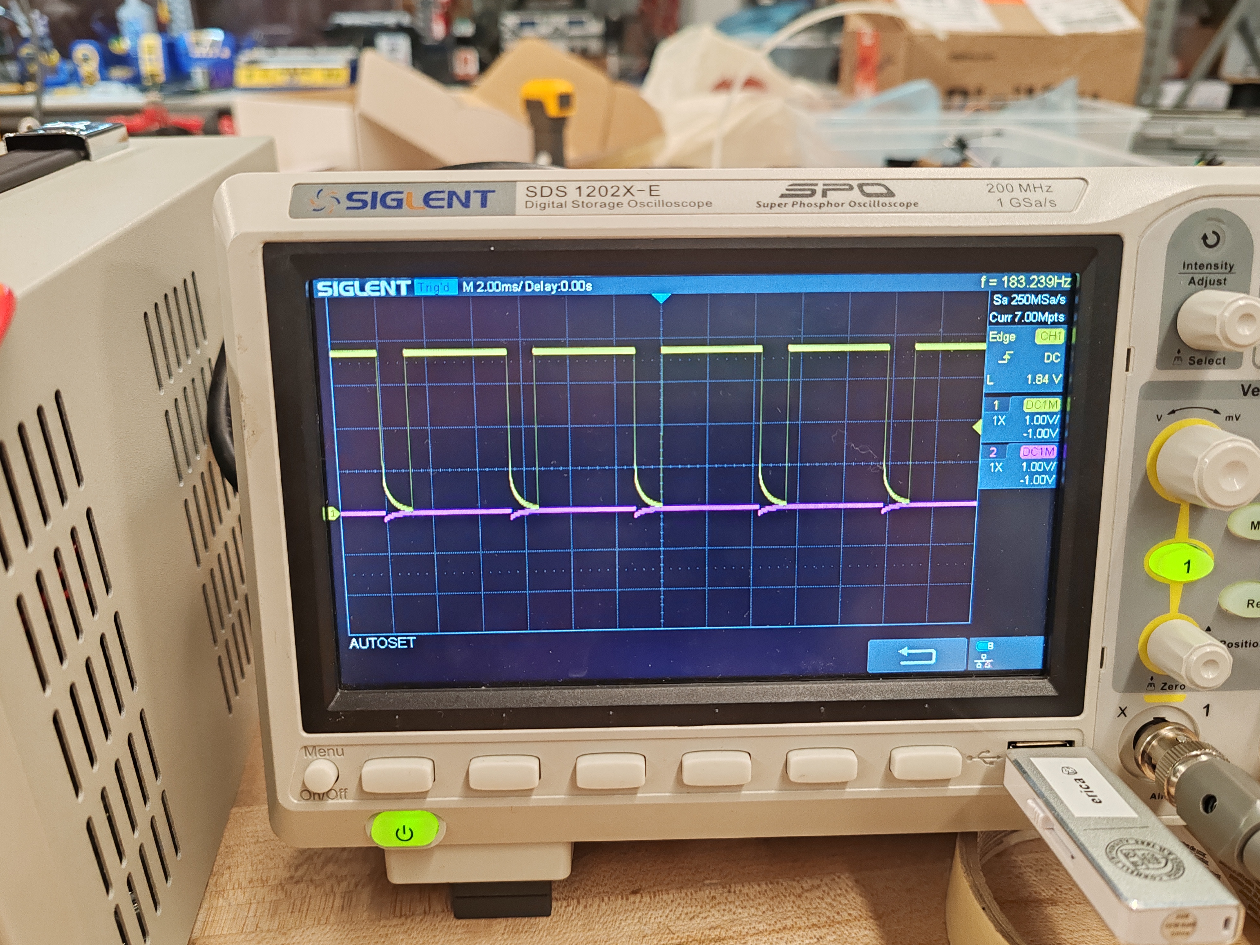 Resulting Signal on the Oscilloscope.
Testing Motor Functionality
Now that we've verified the signals generated are correct, we could now solder the motor drivers to the motors of the car themselves. One motor was tested at a time, with the code shown below used to test them out by driving a forward signal followed by a reverse signal. In this setup, the motor drivers are still being powered by the external power supply.
 Code used to test individual motor functionality.
Showcasing one motor spinning forwards and backwards.
This same test was performed on the other motor and we confirmed that both were working as expected. The next step was now to put the motors back into the car and to solder on the power and ground lines of the motor drivers to the battery port within the car so that we could now test powering the motors using our battery instead of the external power supply. The video below shows the result of the same code we used earlier driving both motors simultaneously.
Showcasing both motors spinning and being powered by our battery.
Component Installation in the Car
Pictured below is a labelled image of our components on the car. As a precaution against accidentally shorting two wires or pins together through the exposed solder, electrical tape was used to cover the individual boards, and they were also separated from one another for safety and to help reduce EMI. Fixing everything firmly in place was also useful for components such as the IMU so that we could reduce noise caused by the components moving inside the car. The ToF sensors were placed on the front and side of the car as was outlined in the last lab, and the Artemis board and its connected battery were kept together in the back compartment where it would convenient to plug in our USB-C cable whenever we would need to flash in new code.
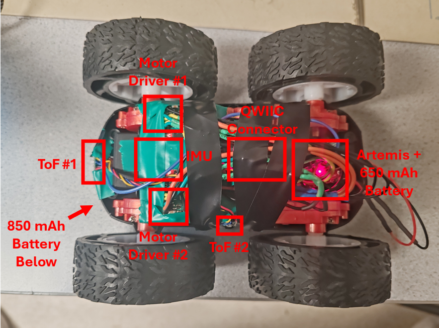 Labelled Image of our component setup.
Lower Limit PWM Value
In order to more efficiently determine the lowest PWM value we could input to the motors and have them move the car without manually flashing in new code to the Artemis board every time. We setup a Bluetooth command where we could input the individual PWM values for the motors on our PC. This made testing quite simple, and an eye test was used to determine whether or not we had found the lowest PWM value. As seen in the code, in order to prevent the car from driving forward endlessly, which could lead to a crash, a timer would be set each time we sent the command to set the motor's PWM value. Once that timer completed, all the motor's PWM values would be set back to zero, ensuring a safe stop. Additionally, the motors would also automatically be set to stop if the Bluetooth disconnected for whatever reason as a safety precaution.
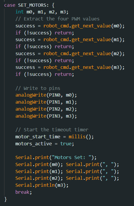 New Bluetooth Command for Testing.
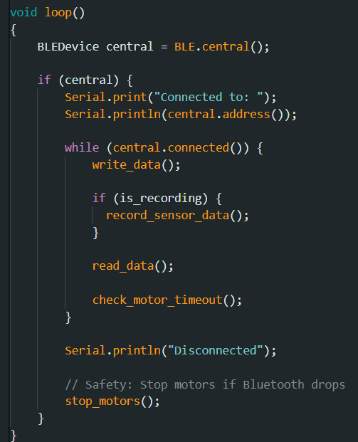 New Main Loop continuously checking if Motor Timer has finished.
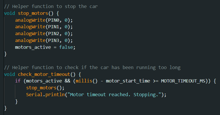 Helper functions used to stop the motors after timeout.
With this new testing ability in hand, through testing multiple values, it was discovered that for driving in a straight line the minimum PWM value was 30 and for turning the minimum PWM value was 100. It should be noted that there was a bit of fluctuation at times where repeatedly running the same PWM values could on some occasions lead to the car moving and on others it not doing anything. The values that we came to were the limits where the car would move fairly consistently. See the videos below for a visual demonstration.
Showcasing the car driving forwards with a 30 PWM value.
Showcasing the car turning with a 100 PWM value.
Calibration and Open Loop Demo
Unfortunately, after further testing, it was clear that when set at the same PWM value, the car would always drift towards the left when attempting to go forwards. As a result, a calibration factor would need to be added as a way to correct the PWM signal and ensure that the car will go straight when we want it to go straight. After further testing using our Bluetooth command, it was found that we need to set the PWM value of the left motor to be 1.2 times what was set for the right motor in order to get the car to remain relatively straight. In order to prevent accidentally going over the max PWM value however, it was decided to have the calibration factor be used to decrease the PWM value of the right motor by the inverse, so 5/6. This would ensure that when were trying to set the PWM values very high, such as above 200, we wouldn't cross over the 255 limit accidentally. As shown in the video, with each tile measuring around 1 foot, the car is shown driving straight for a distance of over six feet.
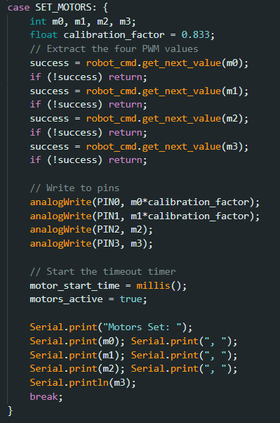 Updated command using our new calibration factor.
Showcasing the car driving straight for over six feet.
Finally, as a last demo for this lab the car was programmed to do a series of moves, including turns, using the new updated Bluetooth command. As a whole, this lab was helpful in gaining experience in soldering, but also allowing us to gain a better understanding on how to integrate systems together in one complete package.
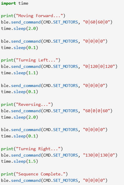 Python code used to command the robot.
Video Demo of the Car Driving Around.
Katarina Duric's website from SP25 was used to help inspire elements of this lab.