Lab Introduction
The goal of this final lab was to implement a closed-loop controller capable of balancing the robot upright on its two wheels, effectively turning it into an inverted pendulum. This is one of the most challenging classical control problems because the system is inherently unstable: any deviation from the balance point is amplified by gravity, requiring continuous, fast corrective action to prevent a fall.
The approach taken was to start the robot in the upright position and apply a PID controller that continuously estimates the robot's tilt angle and drives the motors to correct any deviation from the target balance angle. The sensor pipeline builds directly on the Kalman Filter developed in previous labs, fusing DMP quaternion data from the ICM-20948 IMU with raw gyroscope measurements to produce a reliable, low-latency pitch estimate running at approximately 200Hz. PID commands are sent wirelessly over BLE from a Jupyter Lab notebook, enabling rapid in-the-field gain tuning without reflashing the Artemis.
This lab is intentionally open-ended. The implementation choices, challenges encountered, and lessons learned during tuning are documented below, including an honest account of the difficulties that prevented achieving fully autonomous balancing within the available time.
Angle Estimation: Kalman Filter with DMP Correction
Reliable, low-latency angle estimation is the most critical prerequisite for an inverted pendulum controller. Raw accelerometer data is too noisy for direct use, and gyroscope integration drifts over time. The solution developed here fuses both sources using a Kalman Filter, seeded and periodically corrected by the DMP (Digital Motion Processor) built into the ICM-20948.
IMU Axis Convention
An important hardware detail: the IMU on this robot is mounted sideways relative to the chassis forward direction. As a result, the balancing tilt axis corresponds to the IMU's roll axis rather than pitch. The correct DMP quaternion extraction formula uses the roll formula:
Correspondingly, the gyroscope axis used as the KF prediction input is gyrX() rather than gyrY(). Getting this axis mapping correct was essential: using the wrong gyro axis caused the Kalman Filter to integrate drift in the wrong direction, producing a prediction that slowly diverged from the DMP measurement at every correction step.
Kalman Filter Implementation
The KF state vector is [pitch, pitch_rate]. The prediction step integrates the gyroscope reading forward in time, and the correction step fuses in the DMP quaternion angle whenever a fresh DMP reading is available. The process noise matrix Q is configured to trust the gyroscope heavily, while the measurement noise R = 0.5 gives the DMP moderate trust:
At startup, the KF is seeded directly from a fresh DMP reading rather than from a zero initial state. A 500ms warmup loop runs the full prediction-correction cycle before the PID controller is activated, ensuring the angle estimate has converged to the true physical angle before any motor commands are issued.
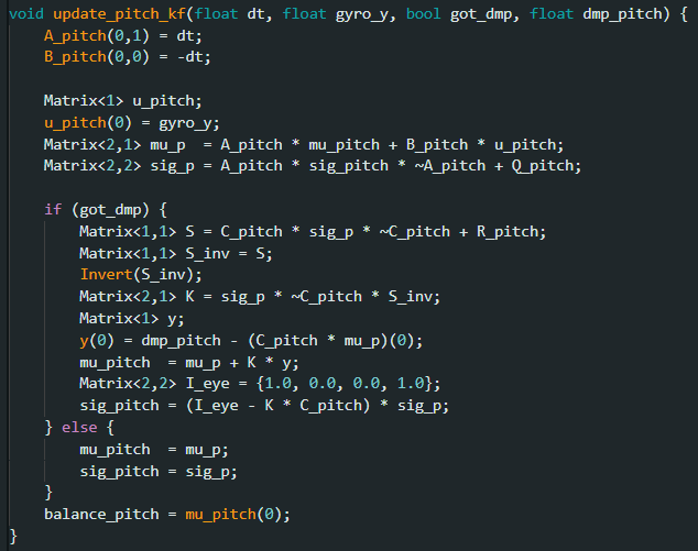
update_pitch_kf() function implementing the full KF predict-correct cycle. Correction is only applied when a fresh DMP reading is available.PID Controller Design
The balance controller is a standard PID acting on the error between the estimated tilt angle and the target balance angle. The control output drives both motors symmetrically since the robot needs to accelerate forward or backward as a unit.
Control Strategy Selection
A classical PID approach was chosen over optimal control methods such as LQR. This decision was driven by prior labs implementing PID controllers, and the same architecture was reused here with the addition of the Kalman Filter angle estimate as the process variable. LQR additionally requires an accurate linear state-space model of the plant, and the severe motor stiction observed on this hardware introduces a highly nonlinear dead zone near the equilibrium point that a linear model would fail to capture. A model-free PID approach augmented with a feedforward deadband offset was more practical given these unmodeled nonlinearities.
Error Convention
The error is negated relative to the raw angle difference so that a forward tilt produces a positive PWM command driving the wheels forward to catch the fall:
Derivative Filtering
The derivative term uses an exponentially-weighted moving average (EWMA) filter with alpha_d = 0.2 to suppress high-frequency sensor noise that would otherwise cause motor chatter. A lower alpha value (less smoothing) was chosen to minimize phase lag in the D term, since excessive smoothing causes the braking force to arrive too late to prevent overshoot. The derivative is computed on error rather than measurement, which is appropriate here since the setpoint is fixed.
Motor Deadband Compensation
The physical motors have a stiction threshold, below approximately 25 PWM the motors do not produce enough torque to overcome static friction and do not move. To ensure that even small PID outputs translate into actual corrective motion, a feedforward deadband offset is applied: any PID output with magnitude greater than 0.5 has MIN_PWM = 25 added before being sent to the motors. The ±0.5 threshold creates a micro-deadzone that prevents the motors from humming or drawing current when the error is virtually zero, while preserving full proportionality for any meaningful correction signal.
Initialization: Seeding the Derivative State
A subtle but important initialization fix: on the very first PID loop iteration, if balance_last_error is initialized to zero but the actual error is nonzero (e.g. 2°), the numerical derivative computes a spurious rate of 400°/s which saturates the motor output immediately. The fix is to seed balance_last_error with the actual error at startup, so the first derivative is approximately zero and the controller starts gently. Similarly, balance_last_filtered_d is seeded with the actual gyroscope reading at activation time to avoid a velocity spike on frame one.
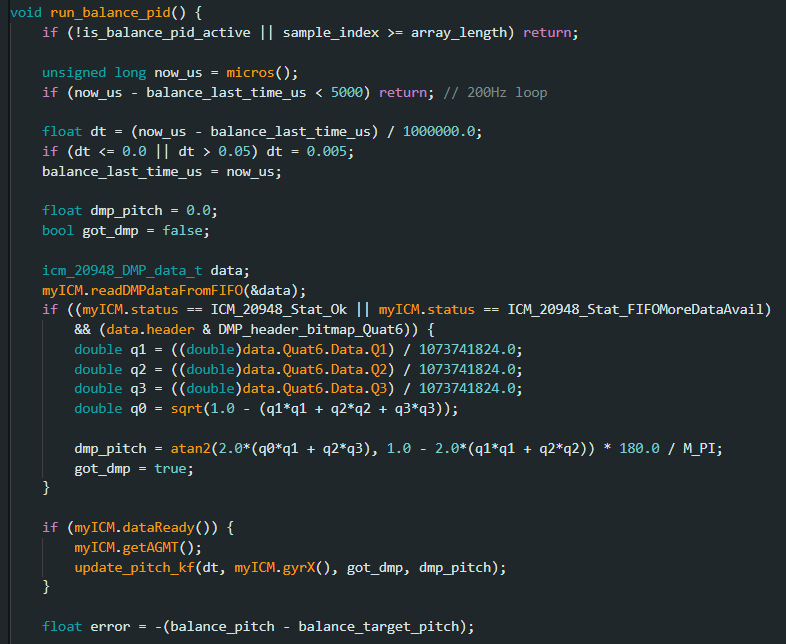
run_balance_pid() function showing the full PID computation, derivative filter, deadband compensation, and data logging pipeline.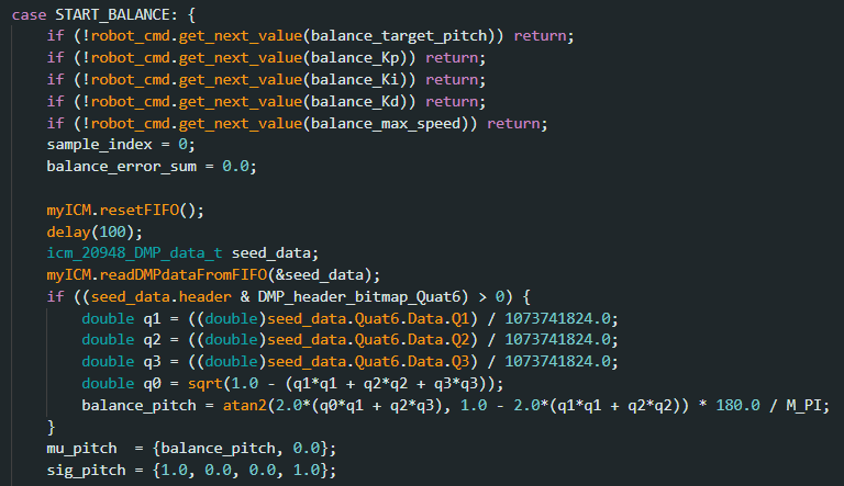
START_BALANCE BLE command handler. Receives target pitch, Kp, Ki, Kd, and max speed over BLE, seeds the KF from DMP, runs the 500ms warmup, then activates the PID.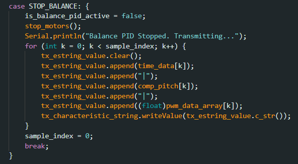
STOP_BALANCE handler immediately kills motors and transmits the full telemetry log back over BLE for analysis.BLE Communication and Python Interface
All PID parameters are transmitted wirelessly over BLE at runtime, which was critical for iterative tuning since reflashing the Artemis for each gain change would have been prohibitively slow. The Jupyter Lab notebook sends a single START_BALANCE command encoding the target pitch, Kp, Ki, Kd, and max PWM as a pipe-delimited string. A notification handler asynchronously receives the telemetry log - 1000 samples of [time_ms | pitch_deg | pwm] - once the PID stops, either via STOP_BALANCE, a safety kill switch trigger, or buffer overflow.
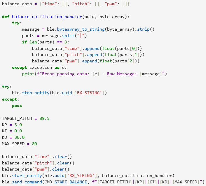
START_BALANCE command. Gains can be updated and a new run started in seconds without touching the robot firmware.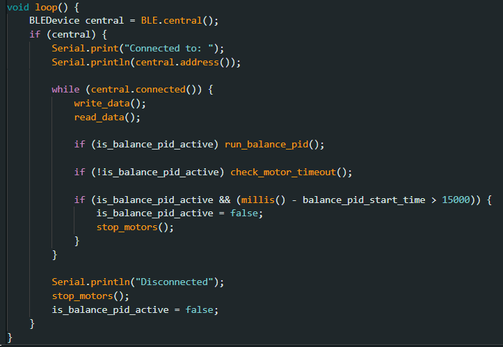
The non-blocking architecture is important: the main loop continuously polls for BLE commands and runs the PID without any delay() calls. The PID function itself uses a microsecond timestamp gate (now_us - balance_last_time_us < 5000) to self-limit to 200Hz, and a 15-second hardware safety timeout automatically stops the motors and flags a fault if the session runs too long.
Balance Point Calibration and Gain Tuning
Finding the True Balance Angle
Before PID tuning could begin, the true physical balance angle had to be determined empirically. The nominal upright angle of 90° is only an approximation: the actual center of mass position, battery placement, and IMU mounting all shift the true equilibrium. To find this, the robot was held manually near upright with the PID running at Kp=0 (motors off), and the pitch stream was observed over BLE while slowly adjusting the hold angle. The angle at which the robot felt mechanically neutral, where it tended to remain rather than fall in either direction, was identified as approximately 89.5° and used as TARGET_PITCH for all subsequent tests.
Gain Tuning Process
Tuning followed a systematic P-then-D approach. Integral gain was kept at zero throughout to avoid integral windup on a falling robot, which causes violent lurching as accumulated error from a fall gets discharged on recovery.
Starting with Kp=5 and Kd=0, the characteristic behavior was a pure proportional response: the robot would react to a tilt but overshoot the target angle, rock back past center, and oscillate with growing amplitude until falling. This is the expected P-only response for an unstable system. Increasing Kp sharpened the reaction but worsened the oscillation amplitude, confirming that Kd was the missing ingredient.
Adding Kd introduced braking force as the robot approached the balance point, but the tuning was sensitive. With the derivative filter at alpha_d = 0.7 (heavy smoothing), the D term arrived too late to prevent overshoot: the filter introduced enough phase lag that braking only engaged well after the crossing event. Reducing alpha_d to 0.2 (light smoothing) produced a faster, more responsive D term that visibly reduced the amplitude of oscillations.
The persistent challenge throughout tuning was the minimum PWM threshold: the motors require approximately 25 PWM to overcome stiction, which means the minimum corrective impulse is always a relatively large lurch rather than a fine micro-adjustment. This creates a structural lower bound on oscillation amplitude that is difficult to tune away.
Results
The plot below shows a representative telemetry run with the robot held manually near the balance point. The pitch angle oscillates around 89.5° in a sawtooth-like pattern, reflecting the human hand making small stabilizing corrections while the PID simultaneously drives the wheels. The relatively tight band around the target angle confirms that the Kalman Filter is producing a stable, low-noise angle estimate and that the PID is reacting in the correct direction to deviations.
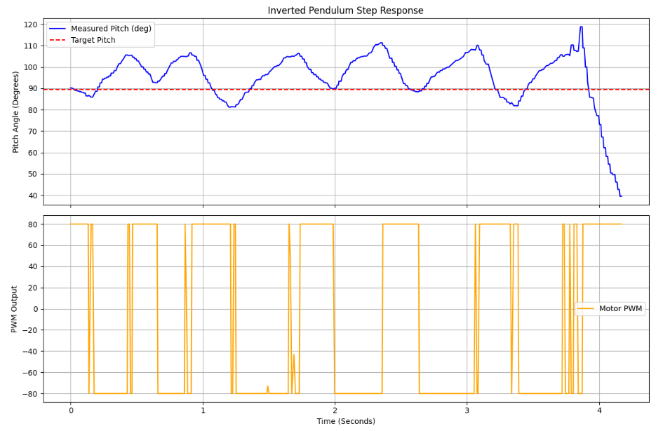
When released without support, the robot consistently exhibited the following failure mode: an initial tilt of 2–5° would trigger a corrective motor command, which due to the minimum PWM threshold was always at least 25 PWM. This produced enough forward/backward acceleration to overshoot the balance point, inducing angular momentum in the opposite direction. The robot would then tilt the other way, trigger another large corrective command, and fall within 1–2 oscillation cycles. The controllable recovery window for this robot is approximately ±5° from the balance point; beyond that, gravitational torque dominates and no realizable PWM output can recover the robot.
What Would Have Helped
In retrospect, the most impactful remaining improvement would have been replacing the numerical derivative term with a direct gyroscope reading as the D input. The gyroscope physically measures angular velocity, exactly the quantity the D term approximates numerically, and using it directly would eliminate the filter lag entirely and make the braking response instantaneous. This was attempted late in the session but encountered a sign ambiguity in the gyro axis that was not fully resolved within the time available. Additionally, the stiction problem near the balance point would likely benefit from gain scheduling — applying a softer Kp within a small window around the target angle to prevent the deadband shift from triggering an overshoot, while scaling Kp up aggressively only when the error exceeds the ±5° recovery boundary where large corrective force is actually needed.
Conclusion
This lab attempted closed-loop inverted pendulum stabilization on the Fast Robots car using a PID controller driven by a Kalman-filtered IMU estimate. The sensor pipeline, DMP quaternion seeding, Kalman Filter fusion at 200Hz on the correct roll axis, and BLE telemetry, was fully implemented and performing reliably throughout testing. The PID architecture included proper derivative filtering, motor deadband compensation, integral windup protection, and careful initialization to prevent derivative spikes at startup.
Autonomous balancing was not achieved. The fundamental limiting factor was the motor stiction threshold, which imposed a minimum corrective impulse larger than what proportional control near the balance point warranted, causing persistent overshoot. Combined with the inherently tight stability window of an inverted pendulum (approximately ±5°), this made the difference between a tuned controller and an uncontrollable one very small in the gains space.
The lab nonetheless yielded a well-understood system: the angle estimate is accurate, the control direction is correct, and the failure mode is well-characterized. With additional time, replacing the numerical D term with a direct gyro velocity feed and implementing adaptive deadband compensation would be the two highest-leverage changes to attempt.